INSTALLATION INSTRUCTIONS FOR THE TURNER TRUCK BRAKE KIT
WHEN ALL ELSE FAILS, READ THESE INSTRUCTIONS!!!
BEFORE YOU START, LOOK AT THE PRE-ASSEMBLED PARTS TO FAMILIARIZE YOURSELF WITH THE LOCATION OF EACH PIECE AND PART! AND BE SURE TO READ THESE INSTRUCTIONS CAREFULLY! AS YOUR SAFETY DEPENDS ON THE PROPER INSTALLATION OF THIS BRAKE KIT!
TO INSURE PROPER BRAKING WITH THIS KIT, A POWER BOOSTER SHOULD BE USED! IF A POWER BOOSTER IS NOT USED, A HARDER BRAKE PEDAL WILL BE EVIDENT.
*IMPORTANT* READ THIS SECTION FOR ALL INSTALLATIONS!
TO ENSURE PROPER BRAKING WITH THIS KIT, THE MASTER CYLINDER MUST BE DISASSEMBLED, AND THE RESIDUAL CHECK VALVE DEFEATED. THIS MUST BE DONE! OTHERWISE BRAKE LINE PRESSURE WILL CONTINUE TO BUILD UP AND EVENTUALLY LOCK UP THE FRONT BRAKES. TO DEFEAT THE RESIDUAL CHECK VALVE, (REFER TO THE SHOP MANUAL FOR LOCATION) EITHER REMOVE THE VALVE ALTOGETHER OR PUNCH A SMALL HOLE IN IT TO DEFEAT ITS PURPOSE! IT IS ALSO NECESSARY TO INSTALL A 10 # CHECK VALVE IN THE REAR LINE.
Remove the stock Studebaker brake parts as per the Studebaker shop manual, be sure to remove everything down to the bare spindle.
CLEAN AND INSPECT THE STOCK STUDEBAKER SPINDLES
CHECK THE ENCLOSED PARTS LIST AND BE SURE YOU RECEIVED ALL THE PARTS
In the kit you will see (2) cup-like machined sleeves, these are called grease seal track adapters. The purpose of these are to space the rotor out to the proper location on the spindle and to provide a machined surface for the grease seal to ride.
This sleeve is purposely machined .002" undersize to the thick part of the spindle so when heated it will expand to slide over the spindle and butt up solid against the face of the spindle. When the sleeve cools, it will shrink fit on to the spindle.
TO INSTALL THE GREASE SEAL TRACK ADAPTERS, A WELDING OR BUTANE TORCH MUST BE USED! DO NOT ATTEMPT TO INSTALL THIS PART WITHOUT HEATING IT UP!
Using a butane or welding torch, and a pair of channel lock pliers, heat up one of the grease seal track adapters, RED HOT, and slide it over the spindle. To make sure that the grease seal track adapter is properly seated up against the spindle flange, use a small piece of pipe and a hammer and GENTLY TAP on the face of the adapter to make sure that it butts up solid against the spindle flange. Repeat the same procedure for the other side.
BE SURE TO GENTLY TAP THE ADAPTER, DO NOT BEAT IT ON!

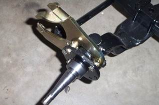
Next install the caliper-mounting bracket, these brackets are marked LEFT & RIGHT! These brackets are mounted to the inside of the spindle flange (toward the engine) by using the back (3) holes on the spindle flange and the upper front hole on the spindle flange.
To install this bracket, use (4) 3/8 x 1 3/4 hex head bolts along with lock washers and lock nuts. BE SURE TO USE RED LOCTITE ALONG WITH THE LOCK WASHERS AND LOCK NUTS! TORQUE ALL THESE NUTS TO 36-38 FT. LBS. Repeat the above step for the other side.
After you have finished mounting these brackets, be sure that the caliper will be in back of the spindle, not in front as originally installed on the Studebakers.
The Cadillac rotors use the same wheel bearing as the Studebaker Car, the Studebaker Car wheel bearing must be used, this is an A-2 and A-6 bearing, and any auto parts store will know which bearings they are. When changing the bearings be sure to change the bearing races in the rotor so they are the correct ones for the bearings. The bolt pattern on the Cadillac rotor is the same as the Studebaker Truck. Be sure to use THE CADILLAC GREASE SEAL for this rotor. Part # 8871
When installing the Rotor, it may be necessary to use 2 axle nut washers to obtain proper adjustment on the wheel bearings.
Now install the Cadillac rotors, after-market R-M rotors (Raybestes # 5028, Bendix 141216), the only difference is the price. These rotors are from 1977 Cadillac Fleetwood’s. And are 12” in diameter.
BE SURE TO ADJUST THE WHEEL BEARINGS AS PER THE STUDEBAKER SHOP MANUAL.

Before installing the disk brake pads, you will notice that on the two stocked G.M. inner pads, a small piece of metal riveted to one end. This is the early warning wear indicator, on some pads, (each manufacture is just a little different in design), this rivet may have to be drilled out and the tab to which it is attached may need to be ground down, to clear the mounting bracket. On most Pads, this procedure is not necessary to do. The pads are D-52
Now the calipers and brake pads are ready for installation on the vehicle.
BE SURE THAT THE CALIPER MOUNTING PINS ARE FOUR (4) INCHES LONG FROM THE END OF THE PIN TO JUST UNDER THE HEAD. GENERAL MOTORS MAKES A NUMBER OF DIFFERENT SIZES FOR DIFFERENT APPLICATIONS! THE CORRECT PART NUMBER IS # 5468226, BE SURE THESE PINS ARE FOUR (4) INCHES LONG TO THE HEAD OF THE PIN, OR 4 1/2 INCHES IN TOTAL LENGTH!
When mounting the calipers be sure to use the LEFT caliper on the LEFT side, and the RIGHT caliper on the RIGHT side, BE SURE THAT THE BLEEDER SCREWS ARE ON THE TOP OF THE CALIPER. The driver’s side of the vehicle is the left side and the passenger side is the right side.

After installing the calipers on the brackets, be sure to look at the brake lines, Wagner part # F98913, this hose is approximately 17 inches long. Before installing the brake line, carefully remove the metal bracket off the hose; be very careful not to damage the hose. I have found the best way to remove this bracket, by clamping the metal bracket in a vise at the hose. Then using a pair of channel lock pliers, bend the metal part of the bracket away from the hose. Be sure to use 2-10 mm crush washers on each hose along with the banjo bolt (G.M. part # 14000404)


All Photos Courtesy of Paul S. Warta
We here at TURNER BRAKE have striven to create the best product along with the ease of installation as we can. However, we cannot install each and every kit on a vehicle prior to delivery, if you or your mechanic do run into a problem. PLEASE let us know, so we can look into it, as we are constantly trying to improve our design.
TO INSURE YOUR SAFETY, We suggest after the first 1000 miles, you should pull one or both sides apart and inspect the spindles, and bearings for abnormal wear patterns. DO NOT REMOVE THE GREASE SEAL TRACK ADAPTERS.
TURNER BRAKE
WARRANTY
This brake kit utilizes, stock American made, modern brake parts from a major automobile manufacturer.
This kit is designed to adapt these modern parts to the stock Studebaker spindles, without any permanent modifications to the spindle. The finest quality parts have been assembled for this kit. All of the bolts, lock washers, and lock nuts are of grade 8 aircraft quality, NOTHING LESS WILL DO!
The stock Studebaker caliper-mounting adapter is held on by 3 3/8 x 1 3/4 grade 5 bolts with lock washers. This kit utilizes 4, 3/8 x 1 3/4 grade 8 bolts, with lock washers and lock nuts.
BE SURE TO USE RED LOCTITE ALONG WITH THE LOCK WASHERS AND LOCK NUTS!
Also included in this kit are the proper torque specifications for each set of bolts,
THESE MUST ALSO BE USED!! A competent professional mechanic should install this kit. THE PURCHASER IS RESPONSIBLE FOR PROPER INSTALLATION OF THIS PRODUCT.
LIMITED WARRANTY
TURNER BRAKE, and it's affiliates, warrants to the original purchaser that it's product shall be free from defects in materials and workmanship for a period of ninety (90) days from the date of original purchase. All claims shall be made by returning the product; FREIGHT PRE-PAID, with proof of purchase to TURNER BRAKE.
If found to be defective in material or workmanship upon inspection, TURNER BRAKE will repair or replace the defective product. In no event shall this warranty exceed the original purchase price of this product.
This warranty shall not apply to products subjected to accident, negligence, alteration, abuse, misuse, racing purposes, improper installation, or unsuited uses. Furthermore, TURNER BRAKE shall not be liable for any consequential, special or contingent damages or injury arising directly or indirectly from any defect in its goods or from use of goods, defective or not.
TURNER BRAKE'S only obligation will be to repair or replace material defects proven to be defective; neither seller nor manufacturer will be liable for any loss, injury, or consequential damages, arising from use or inability to use this product.